

Surface Roughness Measurement: How to Get Reliable Ra and Rz Readings


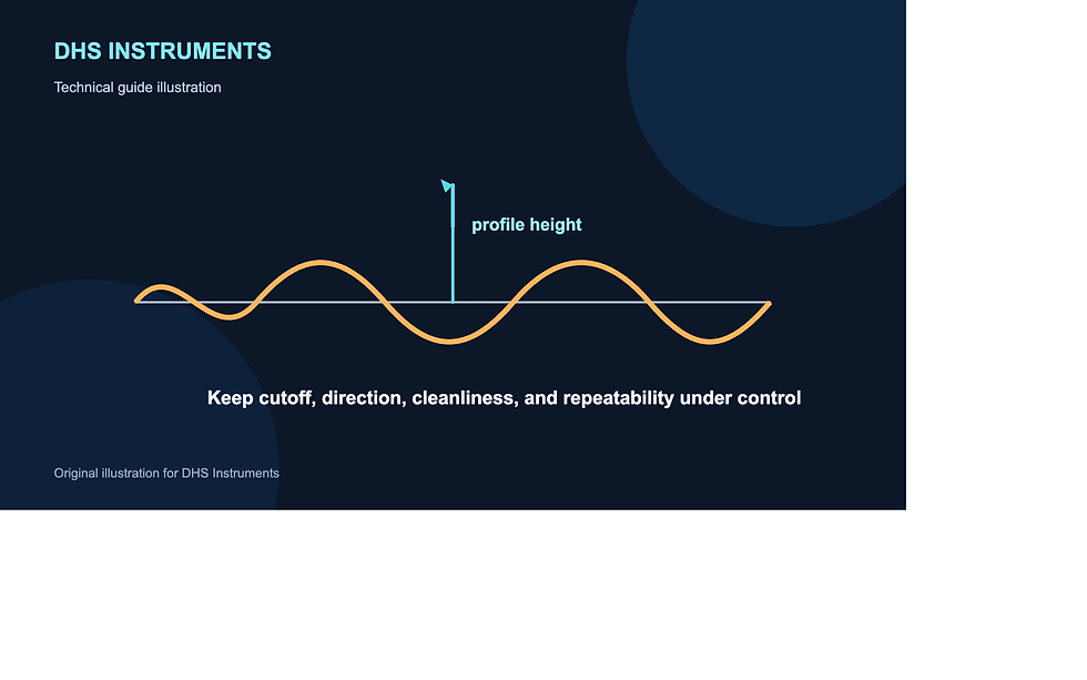
Short answer: Reliable surface roughness measurement requires more than placing a meter on a part. Confirm the parameter and tolerance, measurement direction, cutoff or filter, evaluation length, stylus or sensor, calibration, surface cleanliness, and sampling plan. Ra and Rz values are meaningful only when the measurement conditions are defined and repeatable.
Surface texture affects friction, sealing, adhesion, wear, appearance, lubrication, and the way a coating or component performs. A handheld surface roughness tester can make fast checks, but the operator must understand what the reading represents and what it does not represent.
What is surface roughness?
Surface roughness describes small-scale irregularities on a surface profile. It is one part of surface texture, alongside waviness and lay. The manufacturing process, tool condition, feed, speed, grinding, polishing, blasting, coating, wear, and cleaning can all influence the resulting profile.
Ra is an arithmetic average of profile deviations over a defined evaluation. Rz is a height-based parameter that responds differently to peaks and valleys. Neither parameter describes the entire surface alone. The drawing, specification, or process requirement should identify the parameter, limit, direction, and measurement conditions.
Start with the drawing or specification
Specification item | Why it matters |
Parameter | Ra, Rz, or another parameter may respond differently to the same profile. |
Limit | A maximum, minimum, range, or target requires a defined acceptance rule. |
Lay direction | Measuring along or across grooves can produce different results. |
Filter and length | Settings change which profile features are included in the result. |
Measure across the lay
The stylus or sensing path should normally cross the dominant grooves when the purpose is to capture the roughness created by the process. Measuring along the grooves can produce a lower or different value. Inspect the part and identify the machining direction before placing the instrument.
If the surface has multiple directions, curved geometry, or a non-obvious pattern, record the chosen direction and take additional readings where required. A repeatable orientation is more important than a convenient orientation.
Cutoff, filter, and evaluation length
Cutoff or filter settings separate roughness from longer-wavelength form and waviness. Evaluation length defines the portion of the profile used for the reported result. A reading taken with the wrong cutoff may be numerically precise but technically irrelevant to the specification.
Use the settings stated by the drawing, standard, or inspection plan. ISO 21920 modernizes profile surface texture terminology and specification practice, while older drawings may reference ISO 4287 or ISO 4288. Confirm which document controls the current requirement and how legacy drawings are interpreted.
Choose a surface roughness instrument
Handheld instruments are useful for shop-floor checks, incoming inspection, maintenance, and process comparison. Evaluate the stylus, cutoff options, evaluation length, display, memory, calibration standard, battery, contact force, skid or skidless configuration, and access to the measurement location.
A compact tester may be appropriate for a simple profile check, while a laboratory or production metrology system may be needed for complex surfaces, multiple parameters, areal texture, or traceable reporting. Do not select a handheld instrument when the specification requires capabilities it does not provide.
DHS Instruments lists a handheld surface roughness meter and a related digital surface profile gauge. Confirm the actual measurement parameters, stylus, filters, range, accuracy, calibration, and included accessories before purchase.
Prepare the part and instrument
Clean the surface without changing its texture.
Inspect for burrs, oil, loose debris, scratches, coating, and damage.
Confirm the instrument is within calibration or verification status.
Check the stylus tip and protective components.
Place the instrument securely and align it with the required direction.
Use the specified cutoff, evaluation length, and parameter.
Surface roughness measurement is sensitive to dirt and handling. A fingerprint or a particle can affect the contact. Cleaning must remove contamination without polishing, scratching, or altering the surface being inspected.
Calibration and verification
Use a certified or suitable roughness standard according to the instrument's instructions. Check that the measured reference is within the expected range and that the stylus moves freely. If the result is outside the allowed value, stop production acceptance and investigate the instrument, standard, stylus, settings, and environment.
Verification does not eliminate measurement uncertainty. Record the standard, value, instrument, date, operator, and settings. If the inspection is critical, keep the reference certificate and the result with the inspection record.
Repeatability and sampling
Take a defined number of traces at representative locations. Roughness may vary across a part because of tool wear, vibration, material changes, edge effects, polishing direction, or local damage. A single low reading can hide a poor area.
Repeatability improves when the same operator or trained team uses the same points, direction, pressure, settings, and cleaning method. Marking points or using a fixture may be worthwhile for process studies.
Reading table
Check | Record |
Part | Part number, feature, process, batch, and location. |
Direction | Lay direction and measurement direction. |
Settings | Parameter, cutoff, evaluation length, filter, and unit. |
Result | Individual traces, average, maximum, minimum, and acceptance decision. |
Common causes of misleading results
Wrong direction
Measuring along the lay may not represent the process roughness.
Wrong cutoff
A filter that does not match the specification changes the profile being evaluated.
Dirty surface
Particles and oil can alter the stylus contact.
Damaged stylus
A worn or damaged tip can produce unstable or biased results.
Edge measurement
The geometry near an edge can affect the trace and may not represent the surface field.
Ra versus Rz
Ra averages absolute profile deviations and is widely used for general roughness control. Rz describes a height difference based on profile peaks and valleys under a defined evaluation. Two surfaces can have similar Ra values but different peak and valley behavior. Choose the parameter that relates to the function of the component.
If a customer or drawing names only a general word such as smooth, polished, or rough, ask for a numeric requirement and measurement method. The instrument cannot convert an ambiguous description into a defensible acceptance decision.
How to report surface roughness
Report the part, feature, process, parameter, direction, cutoff, evaluation length, instrument, stylus, calibration reference, individual readings, calculated values, and acceptance rule. Include a sketch or photograph for complex geometry. If the reading is not comparable because of access or surface damage, state the limitation.
Trend roughness when the goal is process control. Rising roughness may indicate tool wear, vibration, incorrect feed, abrasive contamination, polishing changes, or a material issue. A trend helps the team intervene before the surface falls outside the required range.
Planning a repeatable roughness inspection
Define the inspection feature before arriving at the machine. A cylindrical bore, flat sealing face, milled surface, ground shaft, blasted plate, or coated panel may each require a different placement method. Use the drawing, process instruction, or sample plan to identify the relevant surface and direction. If the part has several functional faces, treat them as separate inspection points.
Surface roughness can change during handling. Protect the feature from contact, dust, oil, and packaging material before measurement. Do not wipe aggressively across a direction-sensitive surface. If cleaning is required, state the material and method so operators do not accidentally polish or scratch the area.
Fixtures can improve repeatability on small or curved parts. The fixture should hold the part without distorting the surface or restricting the stylus path. Confirm that the instrument remains level and that the sensing path stays within the specified travel. If a fixture is not available, record how the part was supported.
When a reading is unexpectedly high, inspect the trace or surface rather than immediately rejecting the part. Look for a scratch, burr, chatter mark, tool change, contamination, or an incorrect direction. Repeat at a nearby representative point and compare with the process history. If the result remains high, preserve the trace and escalate according to the quality plan.
When a reading is unexpectedly low, check whether the stylus crossed the intended lay, whether the cutoff excluded important features, and whether the measurement landed on a locally polished area. A low reading can be as misleading as a high reading. The inspection should represent the functional surface, not the easiest point to access.
For supplier selection, ask for the exact parameters, cutoff or filter options, evaluation length, stylus type, measurement range, accuracy, repeatability, display, data storage, calibration standard, and software. Ask whether the instrument supports the drawing symbols and standard used by your customers. Request a sample application review when the surface or geometry is unusual.
Keep a measurement method sheet with a photo or sketch of the feature, direction arrow, settings, number of traces, and acceptance rule. This makes operator training easier and helps compare a new instrument with the current process. A method sheet also explains why two results were not compared when their settings were different.
For process control, combine roughness results with the manufacturing event that may have caused a change. Note tool number, insert condition, machine, program, batch, operator, coolant, and inspection time where relevant. A trend without process context shows that something moved but not what should be corrected.
Use consistent rounding in the report. Do not round a value early and then compare the rounded value to a tight tolerance. Preserve the instrument's displayed or exported result, then state the calculation and rounding rule. If the result is close to a limit, retain the individual traces and the method settings.
Surface roughness is not a substitute for visual inspection, dimensional inspection, profile measurement, or coating adhesion testing. It answers a defined texture question. Combine it with the other checks required by the component's function and specification.
At handover, explain the parameter and direction in plain language. A colleague who sees only an Ra value may assume it is comparable to every other Ra value. The report should make the measurement conditions visible.
These simple controls turn a quick handheld check into a result that can be reproduced, compared, and defended.
If the drawing or customer requirement is ambiguous, request clarification before acceptance. Document the answer so future inspections use the same interpretation and the same measurement settings.
That record protects the inspector, the production team, and the customer when a surface result is later questioned.
Keep the original trace or measurement file where available, not only the final average, so the result can be reviewed later.
Use the same file naming and part identification across inspection and production records.
This keeps a valid reading connected to the correct part and process.
That traceability improves confidence in the final decision.
It also supports better handover.
FAQs
What is Ra in surface roughness?
Ra is the arithmetic average of profile deviations over a defined evaluation. The exact result depends on measurement settings and direction.
Is a lower Ra always better?
Not necessarily. The correct texture depends on function, lubrication, adhesion, sealing, friction, appearance, and the specification.
Why must I measure across the lay?
The direction changes the profile captured by the stylus. Across the lay often gives a more representative result for directional machining marks.
Can a handheld roughness tester measure every surface?
No. Curvature, access, range, stylus, filter, material, and required parameters limit suitability.
How often should a roughness meter be calibrated?
Follow the instrument manual, quality system, standard, and inspection risk. Verify before use and when results are doubtful.
What should I provide to a supplier?
Send the parameter, tolerance, lay, cutoff, evaluation length, part geometry, surface process, reporting needs, and required traceability.
Summary
Reliable surface roughness measurement is a controlled profile measurement. Start with the drawing, set the direction and filter, clean the surface, verify the instrument, use repeatable points, and report the conditions with the result. A meter is useful when the measurement method is as clear as the number.
Useful Sources And Verification
Verify the current drawing, applicable standard, instrument settings, stylus, and calibration reference before acceptance.


Comments