

How to Choose a Coating Thickness Gauge for Paint, Plating, and Protective Films

Short answer: Choose a coating thickness gauge by first identifying the substrate, coating type, expected thickness range, surface profile, measurement environment, and required standard. Magnetic gauges are commonly evaluated for non-magnetic coatings on ferrous substrates. Eddy-current methods are commonly evaluated for non-conductive coatings on non-ferrous substrates. Other applications may need ultrasonic, optical, micrometer, or destructive methods.
The most expensive mistake is choosing a gauge from the product name alone. A gauge that appears suitable may use the wrong principle for the substrate, may not cover the film thickness, or may need a calibration procedure that was not planned. This guide provides a practical selection process for inspectors, fabricators, maintenance teams, coating contractors, and buyers preparing an equipment request.
What does a coating thickness gauge measure?
A coating thickness gauge estimates the thickness of a film or layer applied to a substrate. The coating may be paint, powder, plating, anodizing, zinc, or another protective or decorative layer. The reading is usually reported in a linear unit such as micrometres or mils, but the correct method depends on the substrate and coating system.
Thickness is only one part of coating quality. A coating can meet a nominal thickness and still have problems with adhesion, continuity, cure, porosity, surface preparation, coverage, or contamination. A gauge should therefore support the inspection plan rather than replace it. Define what the reading will approve, reject, compare, or document.
Start with the substrate
Identify whether the base material is ferrous, non-ferrous, conductive, non-conductive, metallic, plastic, concrete, or a layered assembly. The substrate affects how the instrument's field or signal interacts with the coating. A magnetic method is not automatically suitable for every metal, and an eddy-current method is not automatically suitable for every non-ferrous surface.
Also record the substrate shape and condition. Curved parts, small components, edges, thin sheet, rough blast-cleaned steel, hot surfaces, and irregular castings can change the measurement result. The calibration piece should represent the actual substrate and surface condition as closely as practical.
Match the method to the application
Application question | Why it matters |
What is the substrate? | It determines which sensing principle can respond reliably. |
What is the coating? | The layer's electrical, magnetic, acoustic, or optical behavior affects method suitability. |
How thick is the expected film? | The gauge and probe must cover the complete expected range. |
What is the surface profile? | Roughness can influence readings and may require a defined correction or calibration. |
What record is required? | Display-only, statistical, stored, exported, or traceable results need different features. |
Magnetic and eddy-current principles
Magnetic methods are commonly considered for measuring non-magnetic coatings on magnetic or ferrous substrates. The instrument responds to the interaction between the probe and the substrate through the coating. Paint and zinc on steel are common examples, but the exact product range and operating limits must be confirmed.
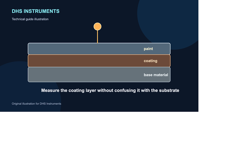
Eddy-current methods are commonly considered for non-conductive coatings on non-ferrous conductive substrates. The instrument responds to changes in an induced electrical field. The coating, substrate conductivity, geometry, and thickness range all matter. If the component contains multiple layers, confirm whether the instrument reports total thickness or can separate layers.
Some products combine methods in one body or accept different probes. That can be useful in mixed inspection work, but the buyer should still specify each substrate and coating combination. Multi-function does not mean that one calibration covers every part.
How calibration and verification affect results
Calibration is the process of adjusting or setting the gauge for a known application. Verification is the check that the gauge is still producing an acceptable result against a reference. Adjustment, verification, and measurement should be treated as separate activities in the inspection procedure.
Use reference shims, foils, blocks, or standards appropriate to the gauge and application. The reference should be known, in good condition, and suitable for the expected range. Follow the manufacturer's instructions and the relevant project or industry standard. NIST publishes coating thickness standard reference materials for magnetic gauges, and ASTM D7091 describes calibration, verification, and adjustment practices for nondestructive dry-film measurement.
Calibration should reflect the substrate, curvature, roughness, temperature, and expected film thickness. A gauge calibrated on a smooth flat coupon may not produce the same result on a rough, curved, thin, or small part. Record the reference used, the setting, the operator, the date, and the acceptance criteria where traceability matters.
Surface roughness and profile
Surface profile is especially important when measuring coatings over blast-cleaned or otherwise roughened steel. The probe responds to the geometry beneath the coating, so a reading may be influenced by peaks, valleys, and the relationship between the film and the profile. ISO 19840 addresses measurement and acceptance criteria for dry-film thickness on roughened surfaces, subject to its stated scope and application conditions.
Do not hide a roughness issue by taking a single reading and reporting it as representative. Define the number and location of readings, the correction method if required, the instrument adjustment, and the acceptance rule. The correct procedure may require a set of readings, not just a single value.
How to take better field measurements
Clean the measurement area without damaging the coating.
Inspect for dirt, grease, loose corrosion, burrs, edges, and visible defects.
Check the gauge on the appropriate reference before measuring.
Place the probe squarely and consistently according to the instructions.
Avoid obvious edges, peaks, holes, corners, and damaged areas unless they are specifically part of the inspection.
Take enough readings to represent the part and the acceptance procedure.
Record the location, substrate, coating system, gauge, probe, and condition.
Measurement technique affects repeatability. Pressing at an angle, sliding the probe, placing it over a defect, or measuring too close to an edge can change the reading. Train operators to use the same sequence and document the method in a short work instruction.
Portable, handheld, and continuous inspection
A handheld gauge is useful when the inspector moves between parts, areas, or production stages. Evaluate grip, display, probe access, battery, memory, data transfer, environmental protection, and the ability to work in the expected temperature and lighting. A portable instrument may be simple and fast, but the inspection plan still needs calibration and recordkeeping.
A continuous or production-line application has additional questions. Define the speed, material presentation, location of the sensor, alarm or control output, and response to surface variation. Confirm whether the selected product is designed for stationary point measurements or continuous monitoring. Do not infer continuous capability from the word continual in a title without reviewing the actual documentation.
DHS Instruments lists several coating measurement options, including a digital coating thickness gauge, a portable ultrasonic coating thickness gauge, and the Coating Thickness Gauge CM-1210A. These are catalog starting points; confirm each model's supported method, range, probes, and included accessories before purchase.
Choosing the probe and accessories
The probe is part of the measurement system, not an interchangeable afterthought. Consider integral or cable probes, tip size, access to small or curved parts, wear, temperature, and the shape of the contact area. A larger probe may help average a rougher surface, while a small probe may provide access but be more sensitive to local geometry.
Ask which shims, zero plates, calibration standards, protective caps, cables, cases, software, and replacement parts are supplied. Confirm whether the quoted configuration includes the probe required for the actual substrate. A body without the right probe is not a complete solution.
Accuracy, repeatability, and acceptance
Separate accuracy from repeatability. Accuracy describes closeness to a reference under defined conditions. Repeatability describes how consistently the same operator or method produces readings. Both matter in a coating inspection program. A published accuracy value is meaningful only with its conditions, range, substrate, probe, and calibration method.
Define the acceptance rule before measurement. A specification may use individual readings, averages, minimum values, maximum values, or a combination. It may also define measurement locations and areas. The gauge cannot decide the acceptance rule unless the instrument and procedure have been configured to do so.
Purchase checklist
Item | Confirm before approval |
Method | Magnetic, eddy-current, ultrasonic, optical, or another defined method. |
Range | Expected minimum, nominal, maximum, and resolution. |
Probe | Type, tip, cable, access, temperature, and included accessories. |
Calibration | Reference standards, adjustment procedure, verification interval, and records. |
Reporting | Display, statistics, memory, export, software, and traceability. |
Common mistakes to avoid
Choosing only by thickness range
A range is not enough if the method does not match the substrate and coating.
Calibrating on the wrong reference
Use a reference that represents the actual material, shape, profile, and expected thickness.
Taking one reading
Coating thickness varies across surfaces. Follow the specified reading pattern.
Ignoring edges and curvature
Geometry can influence a probe. Measure according to the procedure and note difficult locations.
Confusing coating thickness with coating weight
A thickness gauge reports a linear distance. Weight designations may require a separate conversion or standard.
Field inspection planning
Before sending an inspector into the field, define the part identification, drawing or specification, coating system, acceptance criteria, measurement locations, and record format. Use a sketch or marked photograph to show where readings are taken. This helps different operators collect comparable data and makes it easier to investigate a failed result.
Keep the instrument, reference standards, and work instruction together. Protect shims and standards from scratches, dirt, corrosion, and uncontrolled temperature changes. Check the probe tip and cable before use. If the gauge has memory or export, create a file naming convention that connects readings to the part, batch, date, operator, and inspection stage.
When a result is near an acceptance limit, repeat the measurement using the same method and then review the calibration and surface condition. Do not select only the most convenient reading. If the surface has unusual curvature, edges, roughness, or multiple layers, record the condition and escalate the interpretation to the responsible quality or engineering person.
For supplier comparisons, request one clear response that states the method, range, probe, calibration standards, accuracy conditions, software, warranty, manuals, and lead time. Ask which requirements are confirmed and which depend on a sample or application test. This makes the quotation technically comparable and helps prevent an apparently suitable gauge from being ordered without the accessories needed for actual inspection.
These controls turn a handheld reading into a repeatable inspection record that can be reviewed later.
FAQs
What gauge should I use for paint on steel?
A magnetic method is commonly evaluated for non-magnetic paint on ferrous steel, but the exact gauge, range, probe, and calibration must be confirmed for the coating system and surface condition.
Can one gauge measure paint and galvanized coatings?
It may, when both are compatible with the method, substrate, range, and probe. Confirm the configuration rather than assuming that a general coating label covers both uses.
Why does surface roughness matter?
The probe responds to the surface beneath the coating. Roughness can influence readings and may require a defined adjustment, correction, or reading procedure.
How often should a coating thickness gauge be calibrated?
Follow the relevant procedure, manufacturer guidance, quality system, and risk of the application. Verify the gauge before use and whenever conditions or results raise doubt.
Are ultrasonic coating gauges suitable for every coating?
No. Suitability depends on the coating structure, substrate, thickness, surface, and instrument design. Request model-specific confirmation.
What information should I send to a supplier?
Provide substrate, coating system, expected thickness, surface profile, part geometry, environment, inspection standard, measurement locations, and reporting requirements.
Summary
A coating thickness gauge is selected by application, not by title. Start with substrate and coating, then confirm method, range, probe, roughness, calibration, acceptance rule, environment, and reporting. A well-defined inspection brief produces more useful quotations and more defensible field measurements.
Useful Sources And Verification
Verify the current model datasheet, supported substrate, calibration method, probe, and delivery contents before purchase.


Comments