

Clamp-On vs Wall-Mount Ultrasonic Flow Meters: How to Choose

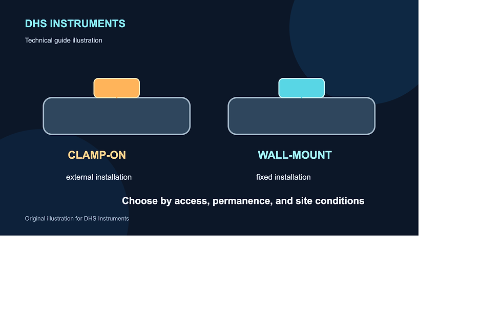
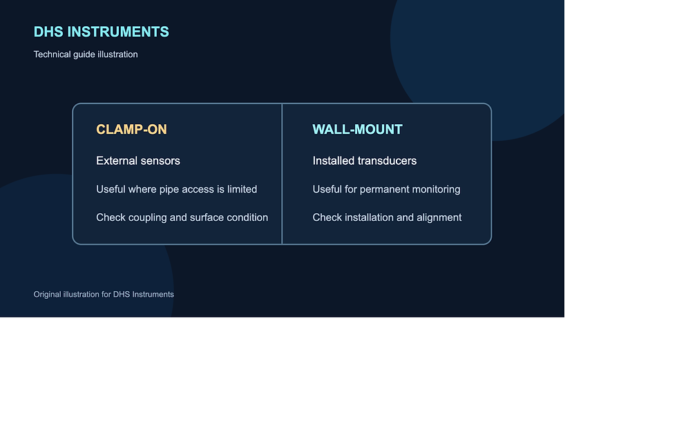
Short answer: Choose a clamp-on ultrasonic flow meter when you need external sensing, temporary measurement, or minimal pipe disruption. Choose a wall-mount arrangement when the electronics need a fixed location for a defined process point. The correct choice still depends on the pipe, fluid, sensor method, power, outputs, environment, and verification requirements.
Clamp-on and wall-mount describe different parts of an installation decision. Clamp-on normally refers to how the transducers attach to the pipe. Wall-mount normally refers to where the transmitter or display is installed. A wall-mount meter may still use externally mounted transducers. Treat the terms as configuration clues, then confirm the complete product arrangement.
What is the practical difference?
A clamp-on ultrasonic meter places sensing elements on the outside of a pipe. The system can be attractive when opening the line is difficult, contamination must be avoided, or the buyer wants a temporary survey. It still requires correct pipe information, a suitable pipe surface, proper transducer positioning, and a signal path that the instrument can detect.
A wall-mount ultrasonic meter places the electronics at a fixed location, often near the measurement point or in an accessible panel area. Wall mounting can make the display and cable arrangement easier to plan for a permanent process installation. It does not automatically define the transducer type, flow principle, enclosure, or output set.
Clamp-on flow meters: when do they make sense?
Clamp-on equipment is often considered for retrofit work, temporary verification, troubleshooting, flow surveys, and locations where cutting the pipe would be disruptive. The external arrangement can reduce the need for a process shutdown, but the installation still needs engineering attention. The pipe must transmit the ultrasonic signal in a way the selected configuration can use.
Clamp-on advantages to evaluate
Potentially less pipework disruption than an inline installation.
Useful for temporary or transferable measurement tasks.
Can support comparison checks at more than one location when the unit is portable.
May be considered where the measured fluid should not contact the instrument body.
These are selection considerations, not guarantees for every model. Confirm the supported pipe materials, diameters, wall thicknesses, liners, fluid conditions, sensor spacing, mounting system, power, and display or logging functions. Review the exact installation instructions before committing to the configuration.
Wall-mount flow meters: when do they make sense?
A wall-mount unit may be suitable when the measurement point is permanent and operators need a fixed display or transmitter location. The arrangement can simplify access for routine review, cable management, and integration planning. It may be used with clamp-on transducers, inline sensing, or another product-specific arrangement, so the buyer should confirm what is included.
Wall-mount questions to answer
Where will the enclosure or display be installed?
What power source and cable route are available?
What environmental protection is required?
Will the meter connect to a control, data, alarm, or monitoring system?
Is the measurement permanent, seasonal, or temporary?
For a fixed installation, do not assess the wall-mount format separately from the pipe and process. Confirm the mounting hardware, cable length, sensor connection, enclosure rating, operating temperature, and service access. A permanent meter is only useful when the installation can be maintained and verified over time.
Comparison table
Decision factor | Clamp-on focus | Wall-mount focus |
Installation | External transducers and pipe access. | Fixed transmitter or display location. |
Best planning question | Can the pipe and fluid carry a reliable signal? | Can the site support permanent mounting, power, and access? |
Typical use | Temporary surveys, retrofit checks, and transferable measurement. | Defined process points and routine monitoring. |
Must confirm | Pipe material, size, wall, liner, fluid, spacing, and mounting method. | Enclosure, power, cables, outputs, sensors, environment, and service access. |
How pipe data changes the decision
Pipe information is essential for both configurations. Record the material, outside diameter, wall thickness, liner, insulation, surface coating, and available straight run. A photograph can help show access and nearby fittings, but it does not replace measured dimensions. If the pipe is insulated or coated, explain whether the sensor can be mounted directly or whether a preparation step is required.
Pipe fullness also matters. A measurement point that is only partly full, exposed to air pockets, or affected by sediment may require a different approach. State the normal operating level and whether the pipe orientation changes with the process. The selected meter's instructions should define the acceptable conditions.
In the DHS Instruments catalog, a handheld clamp-on ultrasonic flowmeter can be considered when the requirement is portable external sensing. A wall-mount ultrasonic flow meter can be considered when the requirement centers on a fixed measurement location. Product titles are starting points; the final choice requires a configuration review.
How fluid condition affects the choice
Ultrasonic measurement depends on how the signal travels through the pipe and fluid. Identify whether the fluid is clean, contains suspended solids, contains gas, changes composition, or operates near a phase boundary. These conditions may affect the suitability of transit-time or Doppler measurement and should be confirmed against the product documentation.
Do not choose by industry label alone. Water treatment, irrigation, manufacturing, chemical processing, and building services can each involve different fluids and pipe conditions. A supplier needs the actual fluid and operating range, not just the industry name. Include temperature, pressure, viscosity if relevant, solids, bubbles, and expected minimum and maximum flow.
Outputs, power, and integration
A clamp-on portable meter may prioritize a local display, battery operation, temporary logging, or a compact setup. A wall-mount installation may prioritize continuous power, a permanent display, pulse or serial outputs, alarms, or integration with a monitoring system. These features vary by model and should be requested explicitly.
Requirement | What to document |
Power | Voltage, frequency, battery or charger needs, and backup expectations. |
Data | Display, totalizer, logging, export, protocol, alarms, or control connection. |
Environment | Temperature, moisture, dust, vibration, chemicals, and access. |
Support | Commissioning, calibration, manuals, training, and replacement parts. |
Installation and verification checklist
Before installation, confirm the selected sensor method, pipe dimensions, transducer location, cable route, and mounting materials. Mark the measurement point and check that the pipe is accessible throughout the commissioning process. Follow the model-specific instructions for coupling, sensor spacing, orientation, and signal setup.
After installation, record the configuration values, operating condition, displayed flow, and any comparison reading available from an approved reference. If the result is unexpected, check the pipe data, signal quality, sensor position, process stability, and fullness before assuming the instrument is faulty.
Common mistakes
Confusing transmitter location with sensor type
Wall-mount describes the electronics location. It does not prove that the sensor is clamp-on or inline.
Assuming external means installation-free
Clamp-on systems still need correct mounting, coupling, spacing, and pipe information.
Using the wrong comparison
A temporary portable survey and a permanent control measurement have different requirements. Define the decision first.
Ignoring documentation
Unconfirmed outputs, accuracy, power, or environmental limits can create avoidable installation problems.
Buyer decision framework
Choose a clamp-on direction when the central need is external sensing, temporary measurement, retrofit flexibility, or comparison work. Choose a wall-mount direction when the central need is a fixed transmitter location, continuous access, permanent power, and process integration. If both descriptions appear in the same product title, ask which part of the system each term describes.
A professional request should include the process, pipe, fluid, flow range, installation point, outputs, power, environment, and verification method. Attach photos and drawings, then ask the supplier to confirm the exact model and included components. This prevents a lower-cost-looking configuration from becoming expensive after installation.
Commissioning and troubleshooting questions
Commissioning should begin with the installation record, not with an assumption that the first displayed value is correct. Confirm the pipe dimensions entered into the meter, the transducer arrangement, the measurement method, the units, the zero or reference condition, and the process state. Record whether the pipe was full and whether the process was stable. These details make the first result traceable.
If the signal is weak or unstable, inspect the pipe surface, coupling, transducer contact, sensor spacing, cable connections, and selected pipe data. Check whether air, sediment, insulation, internal lining, or surface corrosion could affect the sound path. Confirm that the process is within the expected range and that nearby equipment has not created a changing flow profile. A weak signal is a reason to investigate the configuration, not to increase confidence in an unverified reading.
If a clamp-on reading differs from another meter, compare the measurement locations and operating conditions before comparing numbers. Two meters in different parts of a process may see different flow profiles or timing. Confirm that both instruments use comparable units, averaging, totalization, and reference conditions. If the comparison is being used to approve a purchase or process change, document the method and involve the responsible engineering or quality person.
For wall-mount installations, inspect the enclosure location, power quality, cable route, sensor connections, display settings, and communication outputs. A fixed meter may be connected to another system, so the team should confirm whether the displayed value, transmitted value, and recorded value are using the same units and update interval. Label cables and retain the configuration record so future maintenance does not depend on memory.
Build a simple verification schedule that states who checks the installation, how often the reading is compared, which conditions must be recorded, and what action is taken if the result moves outside the expected range. The schedule should match the risk of the process. A temporary troubleshooting survey may only require a documented comparison, while a permanent process measurement may need a more formal review and calibration approach.
The selection decision should also include the people who will operate and maintain the meter. Ask whether they need a local display, a portable case, a fixed panel, a remote signal, or training. Confirm how replacement transducers, cables, coupling materials, batteries, and manuals will be obtained. A technically suitable meter can still create operational friction if its accessories and support are not planned.
When the meter is used for a temporary survey, keep the survey objective narrow. State the question being answered, the period of observation, the locations measured, and the conditions recorded. A temporary result should not automatically become a permanent design value without a review of the method and the process data. When the survey supports a retrofit decision, use the findings to identify what the permanent installation must provide, including access, outputs, protection, and verification.
Keep the final selection brief with the quotation so the supplier can confirm whether the proposed instrument actually matches the process. The brief should state what is known, what is uncertain, and what must be verified before shipment. That simple separation improves technical communication and reduces the risk of a configuration being approved because a familiar product label sounded suitable.
FAQs
Is a clamp-on meter always portable?
No. Clamp-on transducers can be used in temporary or permanent arrangements. Portability depends on the transmitter, mounting system, power, and intended use.
Can a wall-mount meter use clamp-on sensors?
It may, but the product-specific design must be confirmed. Wall mounting describes the electronics or display location, not the complete sensing method.
Which option is better for a retrofit?
Clamp-on may be worth evaluating when cutting the pipe is difficult, but pipe, fluid, and signal conditions still determine suitability.
Do I need pipe measurements before requesting a quote?
Yes. Material, diameter, wall thickness, liner, insulation, and surface condition are important selection inputs.
What should be compared besides price?
Compare measurement method, operating range, installation, accuracy conditions, outputs, power, documentation, commissioning, and support.
Can I use the same configuration for every pipe?
No. The meter must be matched to the actual pipe, fluid, process conditions, and installation method.
Summary
Clamp-on and wall-mount ultrasonic flow meters are not competing labels for exactly the same installation. Clamp-on focuses on external sensing and pipe access. Wall-mount focuses on a fixed electronics or display location. The right choice comes from the measurement objective, pipe, fluid, installation, outputs, environment, and verification plan.
Useful Sources And Verification
Verify the current model datasheet, installation instructions, and delivery contents before purchase.


Comments